
Traction Control
- Thread starter Fubar
- Start date
You are using an out of date browser. It may not display this or other websites correctly.
You should upgrade or use an alternative browser.
You should upgrade or use an alternative browser.
zrchris
GT Owner
One can learn about a great many of Shadowman's innovations by studying the projects on his website. One that showcases the TC install is there now, and I suggest anyone interested go carefully look through the details of this project:
http://www.discovery-automotive.com/portal/module.php?id=projects_hbound
See Phases 3 and 4.
Not for the meek, but not too invasive and well worth the effort.
http://www.discovery-automotive.com/portal/module.php?id=projects_hbound
See Phases 3 and 4.
Not for the meek, but not too invasive and well worth the effort.
How does this traction control system affect the ODB II scanners? When you take it to a Ford Dealer for repairs, is it going to give bad readings since it is not a factory part?
BlackICE
GT Owner
How does this traction control system affect the ODB II scanners? When you take it to a Ford Dealer for repairs, is it going to give bad readings since it is not a factory part?
A custom DA tune is needed to integrate the TC with the ECU and to optimize the performance. I don't believe the tune interferes with any OBDII scans. However if you want to be extra safe it is a simple matter to replace the tune with a non-TC tune and turn off the TC system off before taking the car to a dealer, or any other place that may do a through OBDII scan.
No different than those running Whipple, or TT tunes.
- Aug 25, 2006
- 4,436
A custom DA tune is needed to integrate the TC with the ECU and to optimize the performance. I don't believe the tune interferes with any OBDII scans. However if you want to be extra safe it is a simple matter to replace the tune with a non-TC tune and turn off the TC system off before taking the car to a dealer, or any other place that may do a through OBDII scan.
No different than those running Whipple, or TT tunes.
Thank you BlackICE
You are correct on all issues
Takes care
Shadowman
- Aug 25, 2006
- 4,436
Huuum …… Traction control and the folks that are considering completing the integration processes themselves; I share the following not to discourage but rather in hopes to enlighten many as to just a few of the steps that I take when integrating the traction control system developed specific to the Ford GT. I have had many folks ask me about furnishing the traction control system as a kit. For many it is because of logistics and for others because they truly want to materially participate in the processes. I do understand both reasons and am considering a kit as an option however for those of you that have not visited my website and seen these systems being integrated I want to share some thoughts and a few pictures in the hopes that you recognize that it is not a Saturday afternoon project but rather if “completed” IMO properly it is a scope and magnitude project.
Most folks have come to know that I am all about integrating when compared to simply adding on and in my world the end results must appear as if OEM, remain easy to service by the owner or their caretaker of choice, and that it is not about how long it takes to complete but rather how well it is completed; the key word IMO is “complete” because all too often I see projects finished with folks telling me that because of time constraints they could not complete it and yet it is working and that they intend on completing real soon; all too often the later day never happens.
If I were to present this traction control system as a kit they must be integrated and the project completed otherwise IMO the risk of failure looms and unlike something as fundamental as a dome light that burns out if the traction control system fails then secondary risk could be extreme; one way that I could manage this concern would be not to load the needed software until mechanically the integration had been completed.
The traction control system integration is 95% wiring with a hand full of secondary modules that need to integrated and then plugged in thus allowing shared information between the OEM and secondary systems; the later aka the modules are IMO a no brainer however poor wiring can and often times will turn a delightful idea/project into a fricken nightmare.
You will see that the traction control system is truly integrated using only the best of materials including a variety of gauges of wire depending on the demand of a given component, an endless array of colors including those trace lead so as to better define the task being expected of a given custom harness. I use only Deutsch connectors and this is because they are IMO one of the finest available. They very durable, have a high cycle life, are a multi-seal design, and are extremely easy to service over time
Again I truly do not share any of this to discourage but rather as stated; to inform so that to a person they to some degree understand the project being considered.
Thank you and takes care
Shadowman
The pictures are as follows;
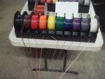
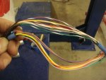
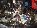
1 and 2 Is an example of the gross wire and some of the colors used
3, 4, and 5 Is the integration at the OEM ABS control module; shielded twisted pair wiring is used and then where the distance is greater than a few inches CAT 7 cabling is used so as to insure that there is no interference presented to the control modules.
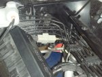
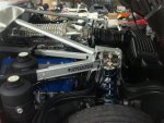
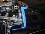
6 and 7 These are pictures of the primary engine harness being completely unwrapped so that secondary systems can be integrated after which the OEM sheathing is installed thus insuring that it appears as if OEM as well as never been touched.
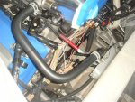
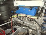
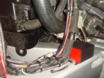
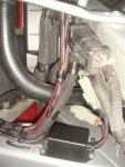
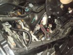
8, 9 and 10 These are of the area at the OEM PCM and the OEM injector controller module; once the integrating of the secondary systems was completed the harnesses and the environment was made to appear as if OEM
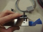
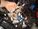
11 and, 12 These are of one of the secondary control modules and the custom wiring harness created for it. The control module is mounted on vibration isolators so as to insure a trouble free service life.
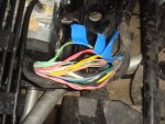
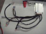
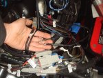
13, 14, and 15 These are of the many custom wiring harnesses located within the boot area aka under the removable front tub of the gal. At this stage the custom harnesses are all terminated with Deutsch connectors, each harness is clearly labeled so that over time anyone can recognize the custom harness application, all of the secondary systems are individually grounded; some even have redundant grounds and then as evidenced in the picture are associated a twisted pair manner with all of them to a common grounding point; specifically the chassis grounding point for the battery to insure a clean signal is maintained to all of the secondary modules. The next phase within the boot area will be to neatly associate all of the secondary harnesses with the OEM harnesses. You can see that the secondary harnesses have all been routed in the same manner as the OEM harnesses so that once this is completed it will appear as if OEM with a fully integrated look.
Most folks have come to know that I am all about integrating when compared to simply adding on and in my world the end results must appear as if OEM, remain easy to service by the owner or their caretaker of choice, and that it is not about how long it takes to complete but rather how well it is completed; the key word IMO is “complete” because all too often I see projects finished with folks telling me that because of time constraints they could not complete it and yet it is working and that they intend on completing real soon; all too often the later day never happens.
If I were to present this traction control system as a kit they must be integrated and the project completed otherwise IMO the risk of failure looms and unlike something as fundamental as a dome light that burns out if the traction control system fails then secondary risk could be extreme; one way that I could manage this concern would be not to load the needed software until mechanically the integration had been completed.
The traction control system integration is 95% wiring with a hand full of secondary modules that need to integrated and then plugged in thus allowing shared information between the OEM and secondary systems; the later aka the modules are IMO a no brainer however poor wiring can and often times will turn a delightful idea/project into a fricken nightmare.
You will see that the traction control system is truly integrated using only the best of materials including a variety of gauges of wire depending on the demand of a given component, an endless array of colors including those trace lead so as to better define the task being expected of a given custom harness. I use only Deutsch connectors and this is because they are IMO one of the finest available. They very durable, have a high cycle life, are a multi-seal design, and are extremely easy to service over time
Again I truly do not share any of this to discourage but rather as stated; to inform so that to a person they to some degree understand the project being considered.
Thank you and takes care
Shadowman
The pictures are as follows;
1 and 2 Is an example of the gross wire and some of the colors used
3, 4, and 5 Is the integration at the OEM ABS control module; shielded twisted pair wiring is used and then where the distance is greater than a few inches CAT 7 cabling is used so as to insure that there is no interference presented to the control modules.
6 and 7 These are pictures of the primary engine harness being completely unwrapped so that secondary systems can be integrated after which the OEM sheathing is installed thus insuring that it appears as if OEM as well as never been touched.
8, 9 and 10 These are of the area at the OEM PCM and the OEM injector controller module; once the integrating of the secondary systems was completed the harnesses and the environment was made to appear as if OEM
11 and, 12 These are of one of the secondary control modules and the custom wiring harness created for it. The control module is mounted on vibration isolators so as to insure a trouble free service life.
13, 14, and 15 These are of the many custom wiring harnesses located within the boot area aka under the removable front tub of the gal. At this stage the custom harnesses are all terminated with Deutsch connectors, each harness is clearly labeled so that over time anyone can recognize the custom harness application, all of the secondary systems are individually grounded; some even have redundant grounds and then as evidenced in the picture are associated a twisted pair manner with all of them to a common grounding point; specifically the chassis grounding point for the battery to insure a clean signal is maintained to all of the secondary modules. The next phase within the boot area will be to neatly associate all of the secondary harnesses with the OEM harnesses. You can see that the secondary harnesses have all been routed in the same manner as the OEM harnesses so that once this is completed it will appear as if OEM with a fully integrated look.
Attachments
Last edited:
So are you suggesting that someone like me, who shouldn't be allowed near a wrench or screwdriver without an insurance policy, should probably avoid trying to install a traction control system on our own ....?
In all seriousness - it sounds like an amazing product for none but the most experienced or brave to attempt to install. Very impressive, as always. Perhaps my gal needs another trip out west. I suspect there are few people on earth who could have designed and implemented a system like this, Shadowman.
Traction Control is indeed the only item I wish my car had, if but for no reason than the added safety of knowing that my right foot's sometimes lack of connection to my brain has someone (or something) looking over my shoulder.
Last edited:
Yes sir...... I am in the middle of integrating two more systems at this time with two more gals presently waiting to be massaged.
Takes care
Shadowman
What is the cost of the system?
- Aug 25, 2006
- 4,436
What is the cost of the system?
Thank you for your interest
PM or email me and I will gladly discuss the system with you
Takes care
Shadowman
- Aug 25, 2006
- 4,436
So are you suggesting that someone like me, who shouldn't be allowed near a wrench or screwdriver without an insurance policy, should probably avoid trying to install a traction control system on our own ....?
In all seriousness - it sounds like an amazing product for none but the most experienced or brave to attempt to install. Very impressive, as always. Perhaps my gal needs another trip out west. I suspect there are few people on earth who could have designed and implemented a system like this, Shadowman.
Traction Control is indeed the only item I wish my car had, if but for no reason than the added safety of knowing that my right foot's sometimes lack of connection to my brain has someone (or something) looking over my shoulder.
Thank you for the kind words
All the best
Shadowman
BlackICE
GT Owner
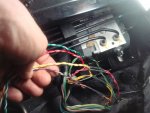
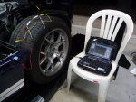
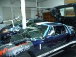
Here are some photos of the R&D work and prototype wiring. Believe me the wiring needed is extreme even if done in expedient way with external routing in the exterior and through the windows. To integrate the wiring as OEM is a order of magnitude increase in time and labor. I you make a error in just one of the critical wires you can fry your ECU, FICM, or ABS controller. Note that the in some of the wire bundles contain two wires of the same color code! Increasing the chance for errors!
IMHO the success rate for a TC kit installation is nil to none, unless the installer is well versed in digital and analog electronics and has the proper diagnostic tools.
IMHO the success rate for a TC kit installation is nil to none, unless the installer is well versed in digital and analog electronics and has the proper diagnostic tools.
Attachments
Last edited:
- Aug 25, 2006
- 4,436
Is that bicycle important? I'd have to get one if it is.
That was his transportation while his gal was under the proverbial knife
Shadowman
BlackICE
GT Owner
That was his transportation while his gal was under the proverbial knife
Shadowman
The bicycle is greener than the Prius!