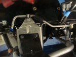
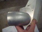
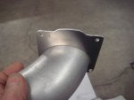
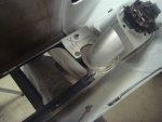
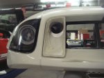
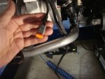
I'm glad Bill has undertaken this project for the many FGT owners on the left coast. It is a difficult, but straight forward project. I'm sure he'll get to installing the ducting and modifying the inner fender liners in his treatise. I had it installed on my gal by the GT Guy (Rich and Dennis) in Scottsdale at Chip's house last year prior to Rally IV. Rocketman (Ron) has also had the brake ducting installed.
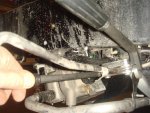
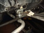
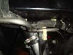
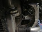
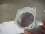
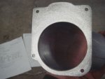
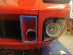
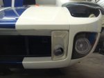
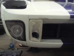
The only non-functional parts on the Ford GT are these duct inlets, and they were originally intended to be functional. They were not installed due to insufficient time to redesign the AC line in order to meet the car's committed launch date. Shadowman, & Rich and Dennis (GT Guy) have corrected this error, and allow our gals to achieve their original intent.