Fubar's GT Build
- Thread starter Fubar
- Start date
You are using an out of date browser. It may not display this or other websites correctly.
You should upgrade or use an alternative browser.
You should upgrade or use an alternative browser.
Looks Good Mark!!!!! do you know by chance how big are the openings at the intake there?
I think it's 2 3/4" maybe 3"
Thanks for the support guys. It's been an arduous journey but I think I see the light at the end of the tunnel. The old blue bird is finally coming back together… although it's more for show than go at this point (PRI to be exact). It still means we have all of the components to build it. Just a few items left to sort through… sensors, N2O lines, connectors, boring stuff.
"BIG" doesn't quite seem to cover it.

BlackICE
GT Owner
Well if you ever get pulled over and asked "didn't you see the flashing red lights in your mirror", you can honestly answer no officer I didn't.
One or two more for good measure.
View attachment 32147
View attachment 32148
If your gona get blown, you might as well get blown big.
get blown or get blown away!!! injection is nice....but i would rather be blown!!!
MoTeC Magic
Spectator
Well... looks like the term "spy" photos is accurate... I'll have to stop sending pics to Mark till after PRI lol... 
Long build... sure... time and money, time and money. More money can make anything go faster but it is usually the limiting variable as it is in our case. I hope that is understandable, and that as it comes together, it starts to click as to why it has taken some time to get here. Mark and I both have ample amounts of time and money in this, neither one of us have a time machine or a cash printing press so that is why we are where we are.
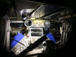
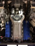
So far all of our time spent in CAD is paying off... currently all pieces fit with the deck lid down with no interferences. It is very tight back there but everything has adequate clearance... so far.
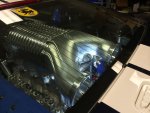
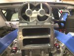
Someone asked about the inlet sizes on the blower plenum... they are 4" inlets. However, there are NO throttle bodies there. The blower is not throttled??? Gasp!!!
I sent Mark a few more images earlier... they'll probably be snuck onto here later I'm sure.
All the best
Well... looks like the term "spy" photos is accurate... I'll have to stop sending pics to Mark till after PRI lol...
Long build... sure... time and money, time and money. More money can make anything go faster but it is usually the limiting variable as it is in our case. I hope that is understandable, and that as it comes together, it starts to click as to why it has taken some time to get here. Mark and I both have ample amounts of time and money in this, neither one of us have a time machine or a cash printing press so that is why we are where we are.
So far all of our time spent in CAD is paying off... currently all pieces fit with the deck lid down with no interferences. It is very tight back there but everything has adequate clearance... so far.
Someone asked about the inlet sizes on the blower plenum... they are 4" inlets. However, there are NO throttle bodies there. The blower is not throttled??? Gasp!!!
I sent Mark a few more images earlier... they'll probably be snuck onto here later I'm sure.
All the best
yes I knew there was no throttle boddies as it did not show them or ONE in the drawings. Are you mounting them farther back or up close to the blower or ??
MoTeC Magic
Spectator
yes I knew there was no throttle boddies as it did not show them or ONE in the drawings. Are you mounting them farther back or up close to the blower or ??
It's a single 4" throttle body that is after the blower and after the intercooler. It is effectively a blow through TB now instead of suck through like a traditional screw charger system. obviously this will flow substantially more air being blow through and will improve drivability during light throttle tip in.
It is a DBW throttle body
I can't stand cables... the DBW system is way more tunable, has great idle control, allows power limitation for boost control by gear and for traction control, great throttle response, etc...
The MoTeC DBW control is proven and works very well with the standard accepted safety protocols.
It also doesn't have the problem the stock GTs throttle cable have of bending the throttle cable bracket allowing the throttle to slightly roll back at higher RPM and airflow values.
Cheers
BlackICE
GT Owner
The main reason OEMs put the throttle body upstream of the blower is so that a light throttle and idle (where all automotive engines spend the vast majority of their lives) the blower is running in a vaccume and essentially unloaded. By placing the TB after the blower, it runs loaded all the time wasting considerable energy compressing air and creating heat.
These may not be concerns in an all out performance build such as this. Essentially the opposite of the way stock GTs react. IE cool air at part throttle and heating up at WOT when the blower is working. This design will actually see hotter air temps (pre intercooler) at part throttle and cool when air flow increases. Of course with the huge intercooler that heat does not enter the engine, it is discharged to the air.
Still very curious why the design went this direction. Fuel economy was obviously not a concern but it is a lot of heat added to the intercooler loop. There must be some benefit you are trying to take advantage of.
All of that was considered. The system is designed to work in conjunction with a wastegate so that, at idle, the unneeded boost is allowed to escape. Because the blower does not work to compress the air (as it freely exits through the wastegate) very little energy is used by the blower. Although The air will meet some resistance moving through the internal intercooler. It will not be quite as efficient as operating in a vacuum but the moving air is used to cool down the intercooler water thereby creating a second point to scrub heat out of the system. When demand for power is given, the ecu closes the wastegate (at whatever % is necessary to create X lbs of boost) and shazaam instant, predicable power is delivered a win/win.
The downside is cost
The downside is cost
Very impressive!All of that was considered. The system is designed to work in conjunction with a wastegate so that, at idle, the unneeded boost is allowed to escape. Because the blower does not work to compress the air (as it freely exits through the wastegate) very little energy is used by the blower. Although The air will meet some resistance moving through the internal intercooler. It will not be quite as efficient as operating in a vacuum but the moving air is used to cool down the intercooler water thereby creating a second point to scrub heat out of the system. When demand for power is given, the ecu closes the wastegate (at whatever % is necessary to create X lbs of boost) and shazaam instant, predicable power is delivered a win/win.
The downside is cost
Please keep us up to date.
Best,
Mark
MoTeC Magic
Spectator
All of that was considered. The system is designed to work in conjunction with a wastegate so that, at idle, the unneeded boost is allowed to escape. Because the blower does not work to compress the air (as it freely exits through the wastegate) very little energy is used by the blower. Although The air will meet some resistance moving through the internal intercooler. It will not be quite as efficient as operating in a vacuum but the moving air is used to cool down the intercooler water thereby creating a second point to scrub heat out of the system. When demand for power is given, the ecu closes the wastegate (at whatever % is necessary to create X lbs of boost) and shazaam instant, predicable power is delivered a win/win.
The downside is cost
Pretty much nailed it...
It does have a wastegate in the system but that is used for boost control. Boost control is by RPM and Gear to create a flat torque curve for each gear. 1st gear will get maybe 500-600 whp, 2nd probably 800-1000whp depending on the tires, and 3rd gear+ will see the rest of the power.
There are 3 blow off valves used to relieve the airflow from the blower since it is moving much more air. The benefit is dramatically cooler running supercharger because instead of recirculating air as the OE system does... it is now continuously moving large amounts of ambient (cool) air through the blower and intake track to cool it down. Also, the hot water coming out of the cylinder head/engine is now bypassed out of the intake manifold with billet water necks that are not attached to the intake and there are phenolic spacers under the intake manifold to prevent heat transfer from the water necks or the cylinder heads to the intake. The blower and intake will run at least 100 degrees F cooler now as proven by our other cars running screw blowers and our hot water bypass kits.
The compressor will not be compressing or working during idle or cruise so it will require a minimal amount of power to turn it.
BlackICE
GT Owner
Are you still using a MAF sensor, if so I assume it is relocated after the blow off valves and between your added inter-cooler and the intake manifold.
Pretty much nailed it...
It does have a wastegate in the system but that is used for boost control. Boost control is by RPM and Gear to create a flat torque curve for each gear. 1st gear will get maybe 500-600 whp, 2nd probably 800-1000whp depending on the tires, and 3rd gear+ will see the rest of the power.
There are 3 blow off valves used to relieve the airflow from the blower since it is moving much more air. The benefit is dramatically cooler running supercharger because instead of recirculating air as the OE system does... it is now continuously moving large amounts of ambient (cool) air through the blower and intake track to cool it down. Also, the hot water coming out of the cylinder head/engine is now bypassed out of the intake manifold with billet water necks that are not attached to the intake and there are phenolic spacers under the intake manifold to prevent heat transfer from the water necks or the cylinder heads to the intake. The blower and intake will run at least 100 degrees F cooler now as proven by our other cars running screw blowers and our hot water bypass kits.
The compressor will not be compressing or working during idle or cruise so it will require a minimal amount of power to turn it.
Thanks to both of you for the explanation. Very interesting. Love this thread and watching the impressive work you are doing.
MoTeC Magic
Spectator
MAF sensor.... lol 
I hate those things....
The MoTeC M150 will be using a MAP, BAP, AT, TP, and RPM sensors, along with a VE table to derive cylinder air mass. It will then use this air mass calculation and a target AF table to calculate a desired fuel mass that will then be converted to a fuel volume and then a duty cycle.... for every single cylinder cycle!
Cheers


