
Possible gauge protection solution CUSTOMER LIST
- Thread starter analogdesigner
- Start date
You are using an out of date browser. It may not display this or other websites correctly.
You should upgrade or use an alternative browser.
You should upgrade or use an alternative browser.
AJK,
Yes, my fault, I will get the necessary information posted within the next few hours.
Thanks, Jay
Yes, my fault, I will get the necessary information posted within the next few hours.
Thanks, Jay
Jay,
You were going to post some options for installing the unit you just made (your post to sr71 page 5). I may have missed that but if I didn't could you please advise.
AJK
AJK,
Please go to the first post and you will see the two schematics. Please let me know if I can be of any more assistance.
Thanks, Jay
Please go to the first post and you will see the two schematics. Please let me know if I can be of any more assistance.
Thanks, Jay
Jay,
You were going to post some options for installing the unit you just made (your post to sr71 page 5). I may have missed that but if I didn't could you please advise.
AJK
Jay,
Thanks for the reply. Correct me if I'm wrong. Installing the first way with the 10 amp fuses if the one fuse blows the gauges still work but the only way you could tell that the fuse blew would be to remove the floor panel to inspect. Using the second method with the 5 amp fuse you are still protecting the system and would know something happened because the gauges go out. Unless I've missed something I am thinking the 5 amp fuse program is the better way to go.
Thanks for the reply. Correct me if I'm wrong. Installing the first way with the 10 amp fuses if the one fuse blows the gauges still work but the only way you could tell that the fuse blew would be to remove the floor panel to inspect. Using the second method with the 5 amp fuse you are still protecting the system and would know something happened because the gauges go out. Unless I've missed something I am thinking the 5 amp fuse program is the better way to go.
Alternate possible gauge protection configuration
AJK,
You are correct in all cases! This was a problem for my car since my fuse block is very busy with other fuse taps that were installed for my wideband O2 sensor. I am now working on a isolated DC to DC converter that will provide maximum protection and this will provide very clean, controlled turn-on, regulated gauge power. I will add some more info to the schematic that I posted later.
Good luck, Jay
Jay,
Thanks for the reply. Correct me if I'm wrong. Installing the first way with the 10 amp fuses if the one fuse blows the gauges still work but the only way you could tell that the fuse blew would be to remove the floor panel to inspect. Using the second method with the 5 amp fuse you are still protecting the system and would know something happened because the gauges go out. Unless I've missed something I am thinking the 5 amp fuse program is the better way to go.
Until the DC to DC converter is available from Jay (Thanks Jay), I would think the 5A/15A or the 5A/20A fuse is the better way to go, yes ?
A coupe of questions (just to clarify):
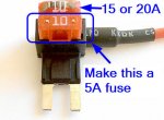
Is method 2 a 5A/15A combo or a 5A/20A combo ?
Where are the fuses placed ? (i.e. replace the 10A fuse in Jay's unit with a 15A or a 20A ? and put the 5A fuse in the empty slot of Jay's part ?-
No to be critical, but I agree with AJK's post #84, method 2 will "flag" a blown fuse without you checking the fuse box (the hint is non functional gauges)
Method 1 (10A/10A) will only light the fuse but you can't readily see that, and the gauges are still functioning, so what happens in the event of another surge ? (do we still have Jay's designed protection ?)- Thanks.
A coupe of questions (just to clarify):
Is method 2 a 5A/15A combo or a 5A/20A combo ?
Where are the fuses placed ? (i.e. replace the 10A fuse in Jay's unit with a 15A or a 20A ? and put the 5A fuse in the empty slot of Jay's part ?-
No to be critical, but I agree with AJK's post #84, method 2 will "flag" a blown fuse without you checking the fuse box (the hint is non functional gauges)
Method 1 (10A/10A) will only light the fuse but you can't readily see that, and the gauges are still functioning, so what happens in the event of another surge ? (do we still have Jay's designed protection ?)- Thanks.
junior,
You are correct in all of your comments.
Method #2 can be either a 5A/15A OR a 5A/20A (even 5A/30A) setup. The reason why it's not critical is that it's only important that the larger (15A or 20A) fuse be much larger in value that the 5A fuse. In case of an overvoltage (or reverse voltage situation), the weaker 5A fuse will blow, thus interrupting voltage to the gauges. Technically speaking, the larger fuse could even be a dead short (only with the Method #2 configuration), since in an overload situation, the 5A fuse will always blow.
Now, the latest news is that I have been making a lot of voltage and current measurements on the gauges in my car and I feel that there are some serious problems when the ignition key is turned ON. I have been designing a new DC-DC converter that will be the ultimate gauge protection device. I hope to have a prototype built within the next two months. I will keep everyone posted on this. Thanks, Jay
Attachments
BlackICE
GT Owner
Jay can you share with the curious what the waveform of the gauge supply looks like during startup. I tried once, but I only have a cheap slow PC USB digital scope and could see anything alarming.
Yes, please give me a day or two!
Jay can you share with the curious what the waveform of the gauge supply looks like during startup. I tried once, but I only have a cheap slow PC USB digital scope and could see anything alarming.
bret a ewing
GT Owner
- Nov 29, 2006
- 302
Jay,
Have you heard of a gauge failure after the installation of your device? I have probably 25-30 starts on the car since protected.
Bret.
Have you heard of a gauge failure after the installation of your device? I have probably 25-30 starts on the car since protected.
Bret.
Bret,
No! However I do not sleep well at night thinking about that possible moment...
I am working on a far superior DC-DC converter. The quality of power going to the gauges with be a night and day difference. More on this as I proceed on this new project. Jay
No! However I do not sleep well at night thinking about that possible moment...
I am working on a far superior DC-DC converter. The quality of power going to the gauges with be a night and day difference. More on this as I proceed on this new project. Jay
Jay,
Have you heard of a gauge failure after the installation of your device? I have probably 25-30 starts on the car since protected.
Bret.
Red-Rocket
Member
Jay,
I'm new to the forum and a little late to the game on this one but was wondering if you still have any kits available? Thanks.
I'm new to the forum and a little late to the game on this one but was wondering if you still have any kits available? Thanks.
Hi Red-Rocket,
Sorry, I do not any more kits available. I am working on a new project for our gauges and will being discussing this within the next month. Please stay tuned...
Sorry, I do not any more kits available. I am working on a new project for our gauges and will being discussing this within the next month. Please stay tuned...
Jay,
I'm new to the forum and a little late to the game on this one but was wondering if you still have any kits available? Thanks.
Bill Briley
GT Owner
bret a ewing
GT Owner
- Nov 29, 2006
- 302