GT500 Engine Similarities to FGT


Xcentric

GT Owner
Mark II Lifetime
Jul 9, 2012
5,213
Myakka City, Florida
Why does one say billit rids and the other say forged h beam? Are the shelbys I beam and Gt H Beam? And again does any know what rod bolts are used? And how much boost and hp can these stock. Motors handle?

Sorry for so many questions

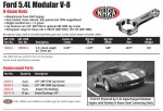
The SAE Technical Paper and the Manley catalog say forged H-beam. The rod bolt PNs are in this pic from the Manley catalog:

manley.jpg
 

Indy GT

Yea, I got one...too
Mark IV Lifetime
Jan 14, 2006
2,526
Greenwood, IN
As jbyrnes, Ralphie and Andy all indicate the SAE collage of 7 technical papers from the 1960 vintage GT-40 and eleven papers covering the development of the 2005-2006 FGT are packed with technical information. I refer to these documents frequently as well. A very good read for those owners interested in the more technical aspects of our car’s development.

Gary, thanks for answering SMOKDU’s question by pointing to the actual Manley catalog. Use of the term “billet” is inexact and most probably used in error describing the Manley rods. A billet is generally defined as “a length of metal that has a round or square cross-section, with an area less than 36 in2 (230 cm2). Billets are created directly via continuous casting or extrusion or indirectly via hot rolling an ingot or bloom.” (reference http://en.wikipedia.org/wiki/Semi-finished_casting_products).

You definitely want forged material properties for a connecting rod duty application and both the GT500 and FGT rods ARE forged steel. The Manley catalogue page states the FGT rods are forged 4340 material and it is likely the GT500 rods are the same material but I do not know for sure. SMOKDU, I know the pictures I posted of the two rod configurations are small (due to posting size limits) but if you look closely the connecting rod cross section of the two are very different. The FGT rod uses a deep “H” fully machined section. This is also shown in the Manley catalogue picture Gary has posted. The GT500 rods are of the typical “I” cross section without a full machining operation on the rod as is typically used for production connecting rods. Nothing wrong with this design and it passed all the internal durability requirements of the GT500 5.4L engine. These rods most likely could have been used in the FGT engine at a significant associated cost reduction were it not for Mr. Coletti’s intervention to insure the FGT engine had the best available internals.

ARP makes very good bolts and they know their business well. The Manley page specifically states the use of ARP rod bolts for this premium connecting rod offering. It is highly likely since Ford sourced our FGT connecting rods to Manley, we have the same ARP bolts in the FGT engine. I do not know what bolts are used in the GT500 engine rod assemblies. They may be ARP or maybe not.

Your final question, “And how much boost and hp can these stock. Motors handle?” I have no idea. Owners of both engine types have certainly modified their engines to deliver significantly more power than originally delivered by Ford. Both engines were designed to deliver 500ish horsepower for the design duty cycle envisioned for their car applications. And development/endurance testing at this design level (likely with margins) was conducted by Ford during development leading to production sign off. Above these horsepower levels, you are your own test department. Trial and error ($$$) will give you your answer. Or go ask Mullet.:biggrin
 

Xcentric

GT Owner
Mark II Lifetime
Jul 9, 2012
5,213
Myakka City, Florida
Horsepower is an imprecise measure of rod strength. Manley cites approximate HP in the catalog image, but caveats that with some of the other variables.

For our engines, being significantly undersquare, rpm may be more of a limiting factor than hp. For such a long stroke design, the 6,500 rpm redline is remarkable and generates insane piston speeds.

The stock rods seem to handle 800 hp ok. We've seen enough Whipples and TTs with stock bottom ends. But while 800 hp at under 6,500 rpm may be ok, far less hp may result in rod failure at over 6,500 rpm.

Boost is another tricky variable. Keep in mind that our stock blowers use 80 hp at full boost. A big Whipple will need well over 100 hp. So, a big Whipple motor needs to make well over 900 hp to put 800 to the output shaft and 7xx to the wheels.

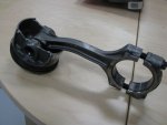
The GT500 websites are full of broken and bent rod photos.

IMG_0229.jpg

BTW, that's an I-beam, but I can't say for sure that it came from a 5.4 GT500.

And, who's to say the rod was too weak for the hp? Maybe the tune was to blame. Or over-revving. Ford was comfortable enough to put the same (or similar) rods in the 5.8 and put a factory warranty on 662 hp.
 
Last edited:

HPGT

GT Owner
Jul 31, 2012
82
Little Rock, AR
Or - it finally caught up with the valve it was chasing.
 

SMOKDU

GT Owner
Dec 17, 2011
412
Thanks for the clear up.

over the years running small block fords we found out the weak links We went from a weaker 2 bolt to a 4 bolt main. It seamed like the weak link was the tune first then rev limiter 2nd. Because we were adding more boost and going to 7500 to 8500 rpm we needed to add strength.

I ran for many years 19 psi boost on a ford racing GT40 create motor ( just the name not a gt40 motor)with cheap hypertechic pistons and I beam rods that were not forged. That combo in a fox body mustang ran 11s in the 1/4 mile . Everyone kept saying I was going to blow it up including ford racing but I tuned the car using an old Anderson ford PMS hand held and was never.greedy on advancing my timing over 17 up high in the RPM. I did after 3 yrs crack the block in half but it was the crank that caused the issue. So this is what I learned by breaking a lot of parts

1. A safe tune and lower rev will make an engine last longer even if you add more boost
2. Cheaper head gaskets act like a fuse and if you miss the tune you will blow them first
3. Getting greedy on the boost and timing kills parts. Adding better parts like forged crank , forged h been rods and ARP 2000 bolts, better blocks,better head bolts ,better upper end heads parts that included stronger valve train parts ie.. Titanium clips and retainers , stronger push rods, better stiffer mounted rocker arms and even better valves .

All this was because we knew our tunes were on the edge and the stress of detonation and heat took a toll on all the stronger parts and easily broke weaker parts. So bottom line is our motors IMO can handle well over 1000 hp unless you miss the tune with not enough fuel or to much timing or over rev the motor . Some ways to reach these higher hp number is to over rev add more timing and run leaner so the circle never ends unless you have better parts or stay safe on the boost and tune. Get it . I lived that story but not yet in the GT but I am on my way.

So adding better parts will help with all the above no matter what engine or car you have. A engine is just a big pump and the stronger you make the parts turning it will determine how much hp any engine can handle. I just wanted to know where and how we broke our engines so far. If I was a betting man I would think tune first, revs second and boost third.

Hope that helps.:wink
 

BAT

GT Owner
Mark II Lifetime
Oct 11, 2012
946
Central Mitten
Great stuff gentleman. Now I am armed with answers for the next car show. For the non-gearheads like me, this is dumbed-down just enough to understand. Thanks again... :thumbsup
 

Indy GT

Yea, I got one...too
Mark IV Lifetime
Jan 14, 2006
2,526
Greenwood, IN
Thanks BAT and others who have expressed appreciation with the comparison information I and others have posted. I am glad the information has been of interest!

SMOKDU, thanks for your experience comments as well. And I agree, the more beefy you can make the engine parts (especially those which reciprocate and spin) the more specific power you can generate reliably. Stresses in rotating parts generally vary by engine speed squared, so small increases in the OE redline limit (which all the tuners love to immediately move higher without much knowledge as to why the limit was set where it was set) can easily push marginal life limit parts to early failures. And if the engine torque curve is falling numerically faster than the over redline rpm limit is increasing, the resultant is decreasing engine power. Thus if you blindly move the redline limit higher just “because”, you can be subjecting the major internal engine parts to significantly higher operating stresses, lowering life expectations all for LOWER engine power. And this concept is hard to convey to most.

There is always a tradeoff between power and engine life. Obviously for an OE manufacturer who sells a product with a prescribed warranty, the engine designers need to develop, test and production deliver an engine which will conservatively deliver the performance metrics AND have sufficient life to make it thru the warranty period and more. The Ford team certainly gave us the performance and life goals with our engine which, looking back at what some of the owners have extracted from their engines, was a very conservative design. Good for them and us, but that was the goal. The FGT was a halo car and it was an important design consideration to not have anything marginal with the powerplant.

Coletti and other engineering managers saw to it that we got a great engine, which we did!
 

PeteK

GT Owner
Mark II Lifetime
Apr 18, 2014
2,267
Kalama, Free part of WA State
Indy, thanks for compiling the great info, and SMOKDU, thanks for the practical observations.

I'm gonna order that SAE book.

Ditto everything SMOKDU and Indy said about higher RPMs putting more stress on engine components. And let me add, that not only do higher reving parts need to be stronger, but they also need to be a light as possible and still survive. Lightening the rotating and especially reciprocating parts buys you more RPM. That's the rationale for using titanium in rods and valve train. How fast do you wanna go? Answer: How much do you wanna spend?

And let me throw in something I mentioned in another thread a few months ago: Rod ratio is important for both longevity and power. Rod ratio is the length of the rod divided by the stroke. The FGT engine (and the other modular V-8's I've looked up) have a rod ratio af 1.6 which is pretty much at the low end of what will last fairly long. The shorter the rod, the greater the angle it makes as the crank goes around. This increased rod angle increases the side loads on the piston which increases friction and wear, and at the other end, on the crank. It also makes the piston travel faster on the downstroke and upstroke, which increases friction and wear. Although I haven't calculated it out or simulated it on engine design software, I also think it decreases the "area under the curve" of the piston-position/time graph, which means it extracts less power out of each combustion event. On the plus side, a shorter rod is lighter and potentially stronger than a long rod, and it allows the cylinder deck to be lower and thus the engine to be smaller and lighter, which can contribute to a lower hood line and lower center of gravity. Smokey Yunick loved high rod ratio engines, and he didn't build slow cars!

Bottom line: If you can put a longer con rod into a special engine you're building, do so.
 
Last edited:

Xcentric

GT Owner
Mark II Lifetime
Jul 9, 2012
5,213
Myakka City, Florida
Lightening the rotating and especially reciprocating parts buys you more RPM. That's the rationale for using titanium in rods and valve train. How fast do you wanna go? Answer: How much do you wanna spend?

Titanium alloy rods were considered and rejected for the GT 5.4.

Computer analysis showed stresses decreased in some rod components and increased in others with titanium. Ultimately, they determined the significantly more expensive titanium alloy would not necessarily increase the life of the rod assembly in the GT application.
 

PeteK

GT Owner
Mark II Lifetime
Apr 18, 2014
2,267
Kalama, Free part of WA State
Titanium alloy rods were considered and rejected for the GT 5.4.

Computer analysis showed stresses decreased in some rod components and increased in others with titanium. Ultimately, they determined the significantly more expensive titanium alloy would not necessarily increase the life of the rod assembly in the GT application.
I'm not surprised. High strength steel is pretty hard to beat. AFAIK, nobody makes titanium cranks for any automotive engine
 

Awsum GT

GT Owner '18
Mark IV Lifetime
Sep 17, 2005
3,985
Carmel & Cntrl Ca
Great stuff gentleman. Now I am armed with answers for the next car show. For the non-gearheads like me, this is dumbed-down just enough to understand. Thanks again... :thumbsup

Really... We can print out a cheat sheet and hand them out to those that ask questions :)
 

Indy GT

Yea, I got one...too
Mark IV Lifetime
Jan 14, 2006
2,526
Greenwood, IN
PowerPoint slide saved as a jpeg for display here. Appreciate any constructive comments.

Obviously, a bit esoteric for the layman, but something to keep in reserve for the know-it-alls and the Top Gear fan boys.

View attachment 37745

Gary,

Went to cars and coffee on Saturday and was just getting out of the car after parking and had a late teen immediately tell me that the FGT engine was the same as in the F150 Lightning truck. :facepalm: I graciously explained that it really was not and tried to recall all the differences off the top of my head. I had not had a cup of coffee yet. He seemed to accept the differences I pointed out but was somewhat reluctant to do so. It's just so appealing to the general public that Ford made this absolutely stunning FGT auto and decided to put a truck engine in it.

I needed your powerpoint slide to hand out to him. Have now made several copies and will keep them in the car for the next occurrence of Oh! same engine as in the Shelby....

Thanks for the slide!
 

Xcentric

GT Owner
Mark II Lifetime
Jul 9, 2012
5,213
Myakka City, Florida
I've been slacking on finishing that slide. To Awsum gave me some good suggestions, but they mean I have more work to do. :lol

I can provide a PowerPoint file that will print a whole lot better than the small jpeg I posted.
 

PeteK

GT Owner
Mark II Lifetime
Apr 18, 2014
2,267
Kalama, Free part of WA State
Horsepower is an imprecise measure of rod strength. Manley cites approximate HP in the catalog image, but caveats that with some of the other variables.

For our engines, being significantly undersquare, rpm may be more of a limiting factor than hp. For such a long stroke design, the 6,500 rpm redline is remarkable and generates insane piston speeds.

The stock rods seem to handle 800 hp ok. We've seen enough Whipples and TTs with stock bottom ends. But while 800 hp at under 6,500 rpm may be ok, far less hp may result in rod failure at over 6,500 rpm.

Boost is another tricky variable. Keep in mind that our stock blowers use 80 hp at full boost. A big Whipple will need well over 100 hp. So, a big Whipple motor needs to make well over 900 hp to put 800 to the output shaft and 7xx to the wheels.

The GT500 websites are full of broken and bent rod photos.

View attachment 37761

BTW, that's an I-beam, but I can't say for sure that it came from a 5.4 GT500.

And, who's to say the rod was too weak for the hp? Maybe the tune was to blame. Or over-revving. Ford was comfortable enough to put the same (or similar) rods in the 5.8 and put a factory warranty on 662 hp.
That picture of a bent rod shows that it failed in compression and buckled. IMO, most likely due to detonation, but also could be due to overboosting or too advanced timing (both of which generally lead to detonation) That was not due to excessive RPM, which would have caused a failure in tension, making the rod stretch or break.
 

PeteK

GT Owner
Mark II Lifetime
Apr 18, 2014
2,267
Kalama, Free part of WA State
Last week, I picked up the SAE book on the FT and GT40--great book, can't put it down! (it is a bit pricey at $90 for a paperback)
 

Indy GT

Yea, I got one...too
Mark IV Lifetime
Jan 14, 2006
2,526
Greenwood, IN
That picture of a bent rod shows that it failed in compression and buckled. IMO, most likely due to detonation, but also could be due to overboosting or too advanced timing (both of which generally lead to detonation) That was not due to excessive RPM, which would have caused a failure in tension, making the rod stretch or break.

Pete is absolutely correct. The bent rod is definitely a compression failure as stated. Failure analysis to the trained eye can tell you a significant amount of information about the failure mechanism.

Although I agree the bent rod is a compression failure, I do not think it is likely the result of overboosting, advanced timing and/or detonation. To be sure these conditions are bad for the piston/rod and do lead to spikes in compression loads transmitted through the rod. However, the extent of the bending to me implies a “time function” failure as it takes some amount of time to bend a rod in that shape. Detonation is a very short duration, high impulse event. Detonation blows holes in the tops of pistons or breaks away pieces of the piston around the circumference. Unfortunately we are not afforded a good view of the top of the piston. And although detonation or over boost could begin the column buckling rod bending event, the engine would start shaking so badly it is unlikely continued engine use could be made to achieve the bent level shape shown in the photograph.

My guess is hydraulic lock where the combustion chamber gets filled with a liquid (oil or coolant) which is uncompressible.

Last week, I picked up the SAE book on the FT and GT40--great book, can't put it down! (it is a bit pricey at $90 for a paperback)

Being a technical person, I thought you might enjoy the papers in this SAE book.:thumbsup
 

2112

Blue/white 06'
Mark II Lifetime
I have seen detonation cause valve train components (springs, retainers and valves) to fail and pieces of valve dropping into the cylinder, preventing full stroke to TDC and bending a rod.

Not saying that is what happened in the picture tho.
 

PeteK

GT Owner
Mark II Lifetime
Apr 18, 2014
2,267
Kalama, Free part of WA State
I have seen detonation cause valve train components (springs, retainers and valves) to fail and pieces of valve dropping into the cylinder, preventing full stroke to TDC and bending a rod.

Not saying that is what happened in the picture tho.
I won't say that detonation CAN'T cause valve failures, but my experience is that it tends to put holes in the pistons, breaks rings and lands, and hammers the bottom end (rods and crank and bearings). Valve failures usually occur when the cam wears down, opens up the valve clearance, which causes the valve to slam into the seat instead of being "gently" lowered onto the seat by the closing ramp profile of the cam (I lost a Porsche 914 engine that way). Also, very worn valve guides will cause the valve to hit the seat at an angle instead of flat on all around its face, which can lead to valve seat recession, the valves not closing completely, and burned valves. However, I've seen some engines with really worn valve guides that still ran okay.

Either way, if the valve head drops into the cylinder, the results can be as you describe. And as Indy surmised, hydraulic lock also will bend rods, which is a fair bet for that rod.
 

2112

Blue/white 06'
Mark II Lifetime
Heck, Competition Cams can and will blame detonation for the immediate failure of their roller tappets (in a pushrod engine) if it makes it your fault and not theirs. :lol