Halfshaft Bolt Answers (all threads merged)


Status
Not open for further replies.

nota4re

GT Owner
Mark IV Lifetime
Le Mans 2010 Supporter
Feb 15, 2006
4,200
By the way, does anyone know if any GT has had a bolt failure after it was repaired by Ford?

Jam,

Yes, at least one and maybe two cars have had the Ford updated parts fail.

Now, for a million dollar question.... please, please, please, can you find out if these 4 pieces were found inside the cupped flange or, alternatively, if the threaded pieces were still in the output shaft. The mechanic who worked on this will know - and it would be VERY valuable info for the members here.
 

Gimbal

GT Owner
Mark IV Lifetime
Jan 11, 2007
204
Queenstown, New Zealand
Jam,

Yes, at least one and maybe two cars have had the Ford updated parts fail.

Now, for a million dollar question.... please, please, please, can you find out if these 4 pieces were found inside the cupped flange or, alternatively, if the threaded pieces were still in the output shaft. The mechanic who worked on this will know - and it would be VERY valuable info for the members here.

It would also be nice to know if the mechanic needed a vicegrip wrench to take the threaded leftover out of the axle. If they were loctited you would think vicegrips would have been needed. Looks like from the picture the threads are oily.
 

Gimbal

GT Owner
Mark IV Lifetime
Jan 11, 2007
204
Queenstown, New Zealand
Good Info! Use a high quality, two flute, tap (NOT made in China, German made are the best!). Use a T-handle on the tap to minimize side loading. Be conservative by threading the tap inward until there is some resistance. Stop and then back it out about 1/2 to 1 full revolution. Then go back in further and repeat. Someone could have a small (hardened) metal burr in one of the threaded holes, so be cautious! When the tap bottoms out it should be very noticable, so do NOT try to cut beyond the factory threads! I have removed more broken taps for friends AND myself than I care to think about. Hopefully we will not have any broken tap stories on this forum. Jay

I was able to just use my fingers to spin the tap in to clean out the threads. I also used loctite primer, this helps the loctite set up more correctly, spray on the bolts and let dry for an hour. I used some "aero duster" with the small tube extension to blow out the debris in the threaded holes. Since the tube fits down into the threaded hole it blows out the debris nicely.
 

Gimbal

GT Owner
Mark IV Lifetime
Jan 11, 2007
204
Queenstown, New Zealand
Nota4re, interesting post and a thought provoker.

The FEA results posted show equivalent stress (ie Von Mesis) so no definition of where the stress is tensile or compressive. From my experience and looking as best I can at the fracture surface shown in the post#626 pictures the failure appears to be tensile overload at the thread fillet-to-head area. It would have been helpful to take a zoomed in picture of just the (under) bolt head fracture surface for better diagnostics. If the bolt is subjected to bending (which is clearly what the FEA indicates by the high stresses (red in color) on one side of the bolt thread) then the Kt effects of the fillet would most likely lead to this type of failure.

I am not sure what "mechanism" you might propose for why the bolts would walk themselves out over time. Sure under torquing the bolts would lead to lower than anticipated preload in both the washer (and drive yoke thru the washer) and the bolt proper, but if Riccardo and or Ford had any QA procedures and locktite was used on the threads, I personally see little chance of bolt relative motion. Yes I know the #626 post does not show any residual locktite on the threads, however it is unclear from the text if these were just as they had been extracted or if a clean-up rag was wiped over the threads. Further, it might be a leap-of-faith to assume bolt under torque condition just because the silver washer does not have a permanent cup. The silver washer was at some time in the design process "bought off" as acceptable for this application and was used in significant numbers in our cars. Production run changes happen all the time which may unknowningly have altered the washer strength so some silver washers were ok and others were not ok in this application.

Accepting your loosening scenerio, if the bolts did loosen (am not sure how far they would actually have to back out, maybe someone can comment) a sufficient distance to allow the splines to disengage (thus the half shaft drive line to the wheel is disconnected from torque output from the transaxle, see Gimbal drawing post #497) there is no torque transmitted. The splines have decoupled. The only way you might possibly get drive torque to the bolts is if the transaxle torque output is channeled through the two bolts loosly screwed into the drive shaft (they have worked loose at this point allowing spline disengagement), the bolts would then channel the torque through the washer and try to drive the decoupled yoke attached to the wheel drivetrain. But since the bolts are loose (ie the washer is loose against the yoke) there is no normal force between the washer and the yoke and thus no means to transmit torque through this interface via friction (mu times normal force which is zero).

Were the bolts failing in torsional shear or just gross torque applied to the upper part of the thread from the transaxle torque migrating to the wheel through the bolts the bolts would show more twisting deformation in my opinion.

Lets hope Ford will come out with a fix for this problem soon.......

Bill

According to my actual measurements the bolts would have to back out approximately .72 inches. The spline engagment is .80 inches. So the threads would need to back out completely before the splines disengaged. But in reality since the splines are so loose as the spline nearly disengaged it could start tilting before the bolts fully backed out. Giving a bit of gas or letting out the clutch could pop the flange off and break the bolts near the end of the bolt. Since the bolts are snapping near the head I feel the bolts are not backing out but being snapped off.

Yep, let's hope FORD or someone else finds the real fix soon!!!!!
 

Indy GT

Yea, I got one...too
Mark IV Lifetime
Jan 14, 2006
2,526
Greenwood, IN
Bolt Failures

Jam, thanks for the additional picture. As best I can tell from the picture it still looks to me as a tensile overload failure as I described. It does not look like a bolt shank torsional failure nor does there appear to be "beachmarks" indicating fatigue (although a closer blow up would be better).

Gimbal, thanks for the measurement weigh-in and I believe that supports my theory that it is unlikely these bolts are backing out almost 0.8" before failure occurs. You would see tale-tale signs on the OD of the threads (I believe) were this occuring just due to relative motion caused by the slight clearance between mating spline profiles. This to me still seems an unlikely failure mode.

Notra4re does ask the germane question as to where the "pieces" were located after the failure. Anyone else experiencing (God forbid) this failure in the future, take note and give us feedback as to where the pieces were after yoke separation. I am sure this would be valuable information for the Ford engineering team (who hopefully watches this post) to design a fix as dealership feedback on this technical issue may not be as concise as our owner findings/observations.

Gimbal, I concur with your thoughts of having to use vice-grips on the remaining thread left in the transaxle shaft IF locktite was used. Since the threads in Jam's picture look pristine it would support the thought that the mechanic just unscrewed the failed threaded portion remaining in the shaft after the bolt head poped off. And maybe locktite was not used on these fasteners. Another important observation to make if someone else has the failure and watches the mechanic fix the car.
 

AZGT

GT Owner
Mark IV Lifetime
Dec 20, 2005
1,354
Scottsdale, AZ.
If the bolts are backing out, why would the shear always be at the head rather than farther down?

Like Gimbal was saying, I would expect to see some signficant tread damage if that was the case. If the torque is enough to snap a head, it is enough to damage threads.

I want to go back to something I mentioned before. The heads look like they have popped off. Could be over torque (rather than under torqued and backing out) or, my idea, that the way the half shafts to wheel assembly is made may be too "short" so that it is putting a horizontal stress (pulling) on the axle - esentially pulling on the axle (the tensil failure which pops the heads) rather than pushing? If the tolerances are too tight, any additional horizontal movement (bigs dips in the road) could be a significant issue. Support for the idea of too much pull is that the shafts DO come out of the transaxle which is why there is no movement of the car and it does the fluid dump.

How about a "push in" design that would creat a floating shaft. Why do the bolts need to be there at all (I know right now they do to hold the cup to bolt the half shaft to, but how about a new cup design) - maybe we need the splined shaft to be like one on a drive shaft in a regular car. Slip in. Those seem to break rarely and they have full engine torque on them all the time. Or, maybe a two piece half shaft with a slip joint that permits floating. Or, what about a shim between the cup and half shaft - where the six bolts are. That would be a cheap fix if t is a pull problem.

Like someone posted, the bolts may just be a symptom, and not the problem.
 
Last edited:

Indy GT

Yea, I got one...too
Mark IV Lifetime
Jan 14, 2006
2,526
Greenwood, IN
AZGT. With respect to your query as to over torque, the failure shown in Jam's picture is NOT caused by over torquing. A torsional failure has a uniquely distinctive characteristic in that it usually appears along a 45deg helix. Take a simple piece of blackboard chalk and twist it in two and you will see what I mean. With a big nod of appreciation to ARP fasteners, their technical section on their web is excellent.
http://www.arp-bolts.com/Tech/TechWhy.html
I have provided some pictures they have of torsional bolt failures-

(Incidently Acufab's half-shaft bolt kit uses ARP fasteners which, in my opinion are superior to the factory bolts either OEM or upgrade kit).

I have not taken my assembly apart so I am limited in my comments without actually seeing the hardware (other than through pictures posted or detailed findings from Forum posters). Typical independent suspension designs all incorporate a provision for lengthening and contracting of the driveline due to irregular road surfaces (pot holes). The distance from the center of the tire to the axle flange does vary and I am sure the engineers have this provision in our car. Note in Gimbals drawing #497 the "CV" assembly just outside the drive yoke. There may be a provision in the assembly. There must be a provision somewhere in the halfshaft for linear (along the halfshaft axis) movement, thus I would not expect there to be any axial loads transmitted to the bolts from the suspension action. Again the FEA done by Analogdesigner (#629) shows the bolts to be undergoing bending which ultimately initiates a crack at the high stress location which unzips the bolt head.

Good dialogue, keep the suggestions coming....
 

Attachments

  • torsion failure.jpg
    torsion failure.jpg
    19.3 KB · Views: 192

AZGT

GT Owner
Mark IV Lifetime
Dec 20, 2005
1,354
Scottsdale, AZ.
AZGT. With respect to your query as to over torque, the failure shown in Jam's picture is NOT caused by over torquing. A torsional failure has a uniquely distinctive characteristic in that it usually appears along a 45deg helix. Take a simple piece of blackboard chalk and twist it in two and you will see what I mean. With a big nod of appreciation to ARP fasteners, their technical section on their web is excellent.
http://www.arp-bolts.com/Tech/TechWhy.html
I have provided some pictures they have of torsional bolt failures-

(Incidently Acufab's half-shaft bolt kit uses ARP fasteners which, in my opinion are superior to the factory bolts either OEM or upgrade kit).

I have not taken my assembly apart so I am limited in my comments without actually seeing the hardware (other than through pictures posted or detailed findings from Forum posters). Typical independent suspension designs all incorporate a provision for lengthening and contracting of the driveline due to irregular road surfaces (pot holes). The distance from the center of the tire to the axle flange does vary and I am sure the engineers have this provision in our car. Note in Gimbals drawing #497 the "CV" assembly just outside the drive yoke. There may be a provision in the assembly. There must be a provision somewhere in the halfshaft for linear (along the halfshaft axis) movement, thus I would not expect there to be any axial loads transmitted to the bolts from the suspension action. Again the FEA done by Analogdesigner (#629) shows the bolts to be undergoing bending which ultimately initiates a crack at the high stress location which unzips the bolt head.

Good dialogue, keep the suggestions coming....

Indy.

Good info.

So the stress on the outside of the bolt heads causes a bend which leads to a crack? I guess the answer to that is to insure that the stress is evenly distributed, which is probably the reasons for the thicker washer and other ideas that guys are working on. Maybe a slightly convex washer so that when it is tightened down serves to make a parrallel surface so stress is distibuted? Or maybe a slightly top hat looking washer so the center can not go concave? If the soft washers are going concave, it means they are not resting against the end of the shaft or the lip on he inside of the cup is too high.

Obviously some of you guys are smarter than I am and appear to be engineers, but the question I still have is, why does the axle pull out of the transaxle? I guess I need to take a tire off and take a good look at the suspension. From just looking at it from the top and looking in the shop manual, I don't see a place for horizontal change, only vertical (since it is upper and lower A-arms, the hub seems to be solidly bolted with shock and toe-in, etc). I would imagine that somehow the vertical movement does travel in an arc that keeps the hub at the same distance from the transaxle? Plus with the axles pulling out, it does indicate a horizontal movement, but where is it? I don't see it. I would also think that with the car basically level there should be some pressure (or neutral) on the half-shafts on the axles. So, again, why do they come out? I don't know if there is something in the CV joints since I can't see in there.

Maybe the horizontal has to do with the "gaps" that have been discussed.

We also kow that there are at least two A-arm types - I wonder if there is more or less (percentage) breakage with one style or another.

Sorry to be redundant, but trying to think outside the bolt created box. As I see it (and would imagine many members do), the problem is not the bolt failure - the problem is "what is producing" the bolt failure.
 
Last edited:

cobrar1339

GT Owner
Mark IV Lifetime
Feb 2, 2006
956
Diamond Bar, Ca
When you read the 600 plus responses I tend to agree with AZ GT here. The speculation in some posts is that the hub and splines mate a bit sloppy.

If so, I would think the torque from rolling on and off the gas could create a rocking motion that may cause the shaft to want to push out. If the fit is not perfectly tight that would cause the splines to rock in the hub.

Once this happens a few times, the bolt would be stretched. If it stretches a bit then you may just get loose enough to create vibration, or does the vibration create all of the above. When the assy rotates do we know it is balanced.

I know from experience, if you cut 50 brake rotors in a row, the first and last are not the same spec. Then, if the guy machining 50 hubs has the same issue we get a stack out tolerance issue. What do we know about this, in regard to the Hubs and other internal parts that could create a balance or shimmy effect. Could it be, the guy who is supposed to check the tolerances on the lathe was not properly trained.

Since it was designed for just two fairly small bolts the specs must be pretty tight, at least on the drawing board. Any wrecked GT's that had bolt failures where we could disect a trans?

Hey I may be off base, but just more food for thought.
 

sharp33

GT Owner
Mark II Lifetime
Apr 19, 2006
346
Rochester, NY
When you read the 600 plus responses I tend to agree with AZ GT here. The speculation in some posts is that the hub and splines mate a bit sloppy...
Since it was designed for just two fairly small bolts the specs must be pretty tight, at least on the drawing board. Any wrecked GT's that had bolt failures where we could disect a trans?..

Or just maybe, since we now know that separation can actually occur at speed, just maybe one of more of the many GT wrecks were caused by this mechanical failure and not driver error. Don't you think that would get Ford moving pronto on a recall and a real fix?
 

Gimbal

GT Owner
Mark IV Lifetime
Jan 11, 2007
204
Queenstown, New Zealand
Indy.

Good info.

So the stress on the outside of the bolt heads causes a bend which leads to a crack? I guess the answer to that is to insure that the stress is evenly distributed, which is probably the reasons for the thicker washer and other ideas that guys are working on. Maybe a slightly convex washer so that when it is tightened down serves to make a parrallel surface so stress is distibuted? Or maybe a slightly top hat looking washer so the center can not go concave? If the soft washers are going concave, it means they are not resting against the end of the shaft or the lip on he inside of the cup is too high.

Obviously some of you guys are smarter than I am and appear to be engineers, but the question I still have is, why does the axle pull out of the transaxle? I guess I need to take a tire off and take a good look at the suspension. From just looking at it from the top and looking in the shop manual, I don't see a place for horizontal change, only vertical (since it is upper and lower A-arms, the hub seems to be solidly bolted with shock and toe-in, etc). I would imagine that somehow the vertical movement does travel in an arc that keeps the hub at the same distance from the transaxle? Plus with the axles pulling out, it does indicate a horizontal movement, but where is it? I don't see it. I would also think that with the car basically level there should be some pressure (or neutral) on the half-shafts on the axles. So, again, why do they come out? I don't know if there is something in the CV joints since I can't see in there.

Maybe the horizontal has to do with the "gaps" that have been discussed.

We also kow that there are at least two A-arm types - I wonder if there is more or less (percentage) breakage with one style or another.

Sorry to be redundant, but trying to think outside the bolt created box. As I see it (and would imagine many members do), the problem is not the bolt failure - the problem is "what is producing" the bolt failure.

Hi AZGT, I think I can explain a couple things. The axles do change length as the suspension does its thing. The CV joints stretch allowing this movement. If, the CV joints had a spring in them pushing out all the time, then maybe the two bolts would not be needed. In fact some drivetrains allow for sliding on the splines to allow this stretching movement. The problem is our splines are not lubricated, so any movement would wear them out. The two bolts prevent spline slop movement and wearing of the splines. The problem is when you prevent something from moving stresses are not relieved, eventually things break. With the washer and bolt trying to prevent movement of the splines I think large load is being imposed on the bolt heads, the weakest link.
 

AZGT

GT Owner
Mark IV Lifetime
Dec 20, 2005
1,354
Scottsdale, AZ.
Hi AZGT, I think I can explain a couple things. The axles do change length as the suspension does its thing. The CV joints stretch allowing this movement. If, the CV joints had a spring in them pushing out all the time, then maybe the two bolts would not be needed. In fact some drivetrains allow for sliding on the splines to allow this stretching movement. The problem is our splines are not lubricated, so any movement would wear them out. The two bolts prevent spline slop movement and wearing of the splines. The problem is when you prevent something from moving stresses are not relieved, eventually things break. With the washer and bolt trying to prevent movement of the splines I think large load is being imposed on the bolt heads, the weakest link.

Thanks. Good info.

So are we preventing movement where there should be movement? Do the CV joints need to stetch more? Slide and be lubricated? Maybe adjustable half-shaft length?

I know that there has been discussion of spline slop, rotational movement, torque, hardness, washers, locktite, etc. With the bolts holding the half-shaft to the axle, and with the problems encountered, obviously there is a stress on the bolts and heads. I know that this has been discussed a lot, but I am not sure we have gotten to why "that" stress is there. My guess is that there is a geometry issue. Seems that looking at the bolts and washer as the problem is doing a patch, not a repair.

Signing off on this one. Just not smart enough :biggrin
 
Last edited:

Gimbal

GT Owner
Mark IV Lifetime
Jan 11, 2007
204
Queenstown, New Zealand
Thanks. Good info.

So are we preventing movement where there should be movement? Do the CV joints need to stetch more? Slide and be lubricated? Maybe adjustable half-shaft length?

I know that there has been discussion of spline slop, rotational movement, torque, hardness, washers, locktite, etc. With the bolts holding the half-shaft to the axle, and with the problems encountered, obviously there is a stress on the bolts and heads. I know that this has been discussed a lot, but I am not sure we have gotten to why "that" stress is there. My guess is that there is a geometry issue. Seems that looking at the bolts and washer as the problem is doing a patch, not a repair.

Signing off on this one. Just not smart enough :biggrin

Right the bolts are pushing the washer which pushes the flange up against the axle bearing. Since there is backlash between the flange and axle only the bolts are trying to prevent movement within the backlash. Eventually the bolt heads break after the axle goes round and round a bunch of times or after enough starts or shifts or clutching.
The CV joints do move in and out an inch or so, I think this is enough. I don't think the CV is hitting its stops but I suppose they could. Certainly if they did I would think it could cause enough load on the bolt heads, but again I don't think this is the problem. The CV is lubricated and sealed within the rubber boot area.
 

Gimbal

GT Owner
Mark IV Lifetime
Jan 11, 2007
204
Queenstown, New Zealand
I also think that the bowing of the soft and even the hard washer to some extent are a factor in the bolts snapping. The bowing of the washer clearly loads up one side of the bolt head. The combo of the spline backlash and bowing are two things that can clearly cause overloading to the bolt heads. Over torque could also be a factor among other things.
A good fix is easy, implementing it and having it affordable are difficult.
 

911teo

GT Owner
Mark IV Lifetime
Jan 5, 2007
628
Surrey, UK
For the records (if someone is keeping track) my car has the upgraded Ford bolts.

Vin # 1606 had the bolts replaced under warranty at 2,500 miles. I found out from the dealer today. I am not sure wether that was done as a precautionary thing or of the OEM had failed.
 

analogdesigner

GT Owner
Mark IV Lifetime
Nov 15, 2005
949
San Clemente, CA USA
Jay at GTsaver.com upgrades his transaxle fasteners:

After many hours of analysis and conversations with numerous individuals on their own experiences, I have finally gotten around to working on my own car and will show some images with comments below. I will be updating this posting over the next several days;

I started on the passenger side. Using my new low-profile, long reach floor jack, I lift the wheel off the ground. For additional safety, I used a scissors jack w/ a "2 x 4" positioned in the central rear of the chassis. The rear wheel is removed:
Jacking%20Car%20SMALL.jpg


GTsaver%20jack%20adapter%20in%20use%20SMALL.jpg


The six CV joint/hub fasteners are removed. A small amount of oil (3-5 cc's) dripped out as expected. Here is what I saw (2005 GT, VIN #1877, 6,971 miles):
Passenger%20side%20coupler%20MED.jpg


My car's VIN number was in the building range of the transaxles with the softer mild steel retaining washers. I used a torque wrench to determine the force needed to break loose each of the two retaining fasteners. In this case 37 ft/lbs for both. This was good news since it suggests that the fasteners had not loosened.

After removing the two fasteners, a dial indicator was installed at the outmost edge of the hub. The hub was then measured for the maximum up-down movement or "slop". Mine measured consistently at 0.021 inch peak to peak. I may ask some of you to assist me in calculating (or double-checking my work) the theoretical clearance between the spline surfaces. Once this value is known, I then have a potential fix for reducing this clearance to any practical value. The hub was ultrasonically cleaned:
Ultrasonic%20cleaning%20SMALL.jpg


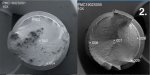
examined and then photographed:
Copy%20of%20Shadowgraph%20of%20coupling%20hub%20w-comments.jpg


I have added comments to the image to show the contact areas of the spline surfaces. The intended contact region for the acceleration side on the spline surface is about 55% of the total face area. Furthermore, about 60-65% of the intended contact region had direct contact with the mating spline transaxle shaft. I define direct contact as any area that has shiny, exposed metal within the blackened surfaces. Now, the deceleration side of the spline had a much reduced direct contact area, about 30-35% of the intended contact region. Furthermore, this region had an oval shaped contact pattern, where the acceleration side was rectangular in shape. When a high level of twisting torque is applied, the mating spline parts will elastically deform resulting in ever increasing direct contact area. With normal use, the force as seen by these parts will be much high when accelerating than decelerating. The maximum deceleration forces would be generated during downshifting of the transaxle.

I am using the fastener kit from Accufab since it's engineering is excellent. Their supplied retaining washers are thicker as well as larger in diameter. The alloy used is also excellent compared to Ricardo's "free machining" soft steel. The ARP fasteners supplied are custom designed incorporating ARP's 2000 alloy, 180 kPSI and 220 kPSI yield and tensile strength respectively. I coated the threaded section and heads of the fasteners with ARP's thread lube, which should have a friction coefficient of about 0.08 to 0.09 when their fasteners are threaded into steel parts.

I used a program called BoltCalc for determining the optimum torque values for the fasteners of concern. This considers all parameters of the fastener and joint interface, too involved to mention here.

I decided to equalize the length of the four retaining fasteners by turning them on my Schaublin 70 watchmaker's lathe:

Turning%20fasteners%20to%20equal%20length%20SMALL.jpg


I center drilled the ends of the fasteners to minimize any small buildup in the center of the fastener during the facing process. The fastener length in my case will end up at 1.3630 +/- 0.0002 inches. This will be double-checked with "Jo-blocks":
Checking%20length%20SMALL.jpg


The importance of this step is that I can remove these fasteners at a later date and remeasure them to check for overstressed situation. Making them the same length just makes it easier, since they do not have to be individually marked. As ARP says, if the fastener has increased in length by more than a "thou" (0.001"), it should be replaced because the fastener has stressed beyond an acceptable yield point. I applied ARP thread lube to the six M10 fasteners and hand threaded them into the hub, making sure that there were no snags which could create an incorrect torque reading during final assembly. I inspected the seal (more on that later), then inserted the hub. The pair of M8 fasteners (with ARP thread lube on the threads and under the head) were hand threaded into the axle. I used several 3/8" drive extensions with a 12 point socket so that I was working "outside of the car". To obtain an accurate fastener torque value, it is recommended that each fastener is torqued to it's final value five times. This was done by gradually torquing both fasteners to 24 ft/lbs., then gradually releasing them to 5 ft/lbs., repeating this operation five times. Remember that this is very interactive, meaning that what happens to one fastener will effect the other one. WARNING! Make sure that when loosening the fasteners from their ultimate torqued value (24 ft/lbs.) that it is done gradually! This means you DO NOT remove only one fastener completely, leaving the remaining one to take the remaining load from the retaining washer! Although I have not calculated this, it is possible that the remaining fastener could be overstressed. I cannot prove this as of yet, however, I would rather error on the side of caution!

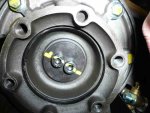
Here is a view of the hub with fastener pair torqued to final value, pre-cleanup:
Coupler%20installed%20w-Accufab%20kit%20SMALL.jpg


The six outer M10 fasteners were gradually torqued to 53 ft/lbs., again, I used BoltCalc to analyze this particular joint. The torque values that Accufab gives in their instructions are fine.

Now, I do not use safety wire or threadlocking chemicals, such as Locktite. Why? Because there should not be enough ultrasonic energy to loosen any of the fasteners that we just mentioned. If the ultrasonic energy is high enough to cause fastener unscrewing, then the transaxle wouldn't last too long, since most of it's internal components would be destroyed in a short order! Safety wiring and threadlock chemicals usually give the person a false sense of security. Think about it, if you are relying on safety wire to hold a mission critical fastener in place, then it is a bad design. The same is true for threadlocking chemicals. Look at the hardened washer "solution". When the heads of the fasteners snap off, you end up with the safety wire holding on to a pair of fastener heads. If a threadlocker was used and the fastener heads snap off, then the remainder of the fastener remains stuck in the axle, meaning that the safety wire or threadlocker did nothing to prevent the problem . Ideally a fastener should be installed so that it is preloaded or stretched (like a spring) to a specific value.

More to come! Jay
See list of GTsaver products at:
http://www.fordgtforum.com/forums/forumdisplay.php?f=34

or www.GTsaver.com
 
Last edited:

Gimbal

GT Owner
Mark IV Lifetime
Jan 11, 2007
204
Queenstown, New Zealand
Hi Jay, Good write up, I learned a lot from your post! The photo of the two bolts and their yellow stripe looks at first glance that one might have rotated since being striped. My yellow stipes were basically horizontal as if the person putting the stripe on went right across both bolt heads. See photo of mine. You might want to put your own stipe across the ARP bolts just for reference.
As for loctite and saftey wire and its use I wonder why critical fasteners on aircraft are nearly always saftey wired?
Thanks for the good work and info.
John
 

Attachments

  • Yellow stripe 1.jpg
    Yellow stripe 1.jpg
    62.4 KB · Views: 269

BlackICE

GT Owner
Nov 2, 2005
1,416
SF Bay Area in California
...Now, I do not use safety wire or threadlocking chemicals, such as Locktite. Why? Because there should not be enough ultrasonic energy to loosen any of the fasteners that we just mentioned...Think about it, if you are relying on safety wire to hold a mission critical fastener in place, then it is a bad design. The same is true for threadlocking chemicals...

Jay, I agree with you 100% about the use of threadlocking and safety wiring. But I had mine safety wired by the GTGuys, because as we all know it is a "BAD DESIGN", and I need that false sense of security. I am not sleeping well until we have a real long term solution. Until then monitoring of the parts in questions is the prudent thing to do.


Also thanks for the wonderful pictures of the area of concern.
 

AZGT

GT Owner
Mark IV Lifetime
Dec 20, 2005
1,354
Scottsdale, AZ.
OK, I lied. Back in.

Jay - does the washer sit flat on the axle, or is there a gap? Was wondering if we need to plastigauge that spot and maybe add a shim?
 

analogdesigner

GT Owner
Mark IV Lifetime
Nov 15, 2005
949
San Clemente, CA USA
Safety wire's real purpose?

Hi Jay, Good write up, I learned a lot from your post! The photo of the two bolts and their yellow stripe looks at first glance that one might have rotated since being striped. My yellow stipes were basically horizontal as if the person putting the stripe on went right across both bolt heads. See photo of mine. You might want to put your own stipe across the ARP bolts just for reference.
As for loctite and saftey wire and its use I wonder why critical fasteners on aircraft are nearly always saftey wired?
Thanks for the good work and info.
John
John,

Good point about the painted stripe! I even own the real thing, in yellow. I just forgot to use it this time. When I pull things apart in a few weeks for a checkup, I will do that!

I think that safety wire is an acknowledgement that the fastener(s) have been torqued and have not moved since. You can easily look at a safety wired setup and visualize if everything is okay. A threadlock compound prevents visual inspection. Safety wire cannot hurt anything, and should be required for any aircraft application. I hope that I do not end up with an arrow in my back making these comments!

Thanks for your comments. I will have more info to add soon, however I must tend to my real job. Jay
 
Status
Not open for further replies.